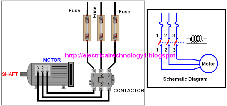
- Control ON/OFF Circuit diagram of Typical Electrically Held lighting/Heating Contactor

- A Simple Circuit Diagram of Contactor with Three Phase Motor.

- Abbreviations: ( FOR Star Delta 3-phase Motor Automatic starter with Timer)
- R , Y, B = Red, Yellow, Blue ( 3 Phase Lines)
C.B = General Circuit Breaker
Main = Mai Supply
Y = Star
Δ = Delta
1a = Timer
C1, C2, C3 = Contatcors (For Power & Control Diagram)
O/L = Over Load Relay
NO = Normally Open
NC = Normally Closed K1 = Contactor (Contactor coil)
K1/NO = Contactor Holding Coil (Normally Open)
Operation and Working Principle of Star Delta 3-phase Motor Automatic starter with Timer:
From L1 The phase current flows to thermal overload contact through Fuse, then OFF Push button, On Push button Interlocking Contact 2, and then C3. This way, the circuit is completed, as a result;
- Contactor coil C3 and Timer coil (I1) is energized at once and the motor winding then connected in Star. When C3 is energized, its auxiliary open links will be closed and vice versa (i.e. close links would be open). Thus C1 Contactor is also energized and Three Phase Supply will reach to the motor. Since winding is connected in Star, hence each phase will get √3 times less than the line voltage i.e. 230V. Hence Motor starts safely.
- The close contact of C3 in the Delta line opens because of which there would be no chance of activation of contactor 2 (C2) .
- After leaving the push button, Timer coil and coil 3 will receive a supply through Timer contact (Ia) , Holding contact 3 and the close contact 2 of C2.
- When Contactor 1 (C1) is energized, then the two open contact in the line of C1 and C2 will be closed.
- For the specific time (generally 5-10 seconds) in which the motor will be connected in star, after that the Timer contact (Ia) will be open (We may change by rotating the timer knob to adjust the time again) and as a result;
Also read;
(I) Starting & Stopping of 3-Phase Motor from more than One Place Power & Control diagrams
(ii) (ON / OFF Three-Phase Motor Connection Power & Control Schematic and Wiring Diagrams)
(I) Starting & Stopping of 3-Phase Motor from more than One Place Power & Control diagrams
(ii) (ON / OFF Three-Phase Motor Connection Power & Control Schematic and Wiring Diagrams)
- Contactor 3 (C3) will be off, because of which the open link of C3 will be close (which is in the line of C2) thus C2 will also energize. Similarly, When C3 off, then star connection of winding will also open. And C2 will be closed. Therefore, the motor winding will be connected in Delta. In addition, Contact 2 (which is in the line C3) will open, by which, there would not be any chance of activation of coil 3 (C3)
- Since the motor is connected in Delta now, therefore, each phase of the motor will receive full line voltage (400V) and the motor will start to run in full motion.
Also Read;
Main Difference between contactor and Starter
The magnetic starter is very similar to the magnetic contactor in design and operation. Both have the feature of operating contacts when the coil is energized. The important difference between contactors and starters is the use of overload heater element in the starter. (For protect the motor from over heating or over load protection)
 home
home


 Home
Home
+ comments + 4 comments
the photos are not so clear
good but timer connection find out clear please
Nicely Explained but Images Should more clear
Star Delta Starters
Mk-1 Contactors
Thanks for posting , i got a clear idea
DOL Starter
Post a Comment